TMAT21X23B68-31-43 | E14R00P04
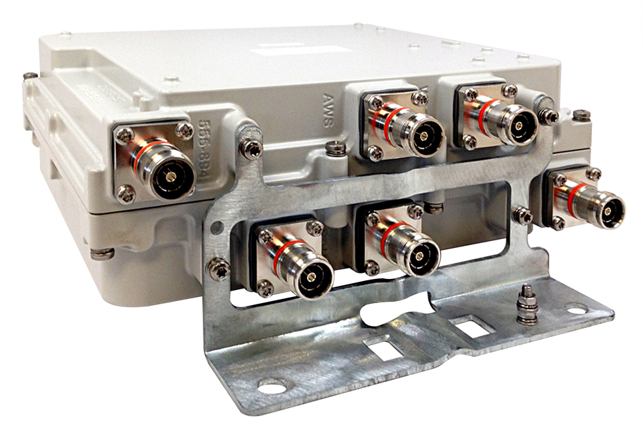
Twin TMA AWS/WCS with 555-894 Bypass, 4.3-10 connectors
Specifications
Product classification
| Product Type | Tower mounted amplifier |
General specifications
| RF Connector Interface | 4.3-10 Female |
| RF Connector Interface Body Style | Long neck |
Dimensions
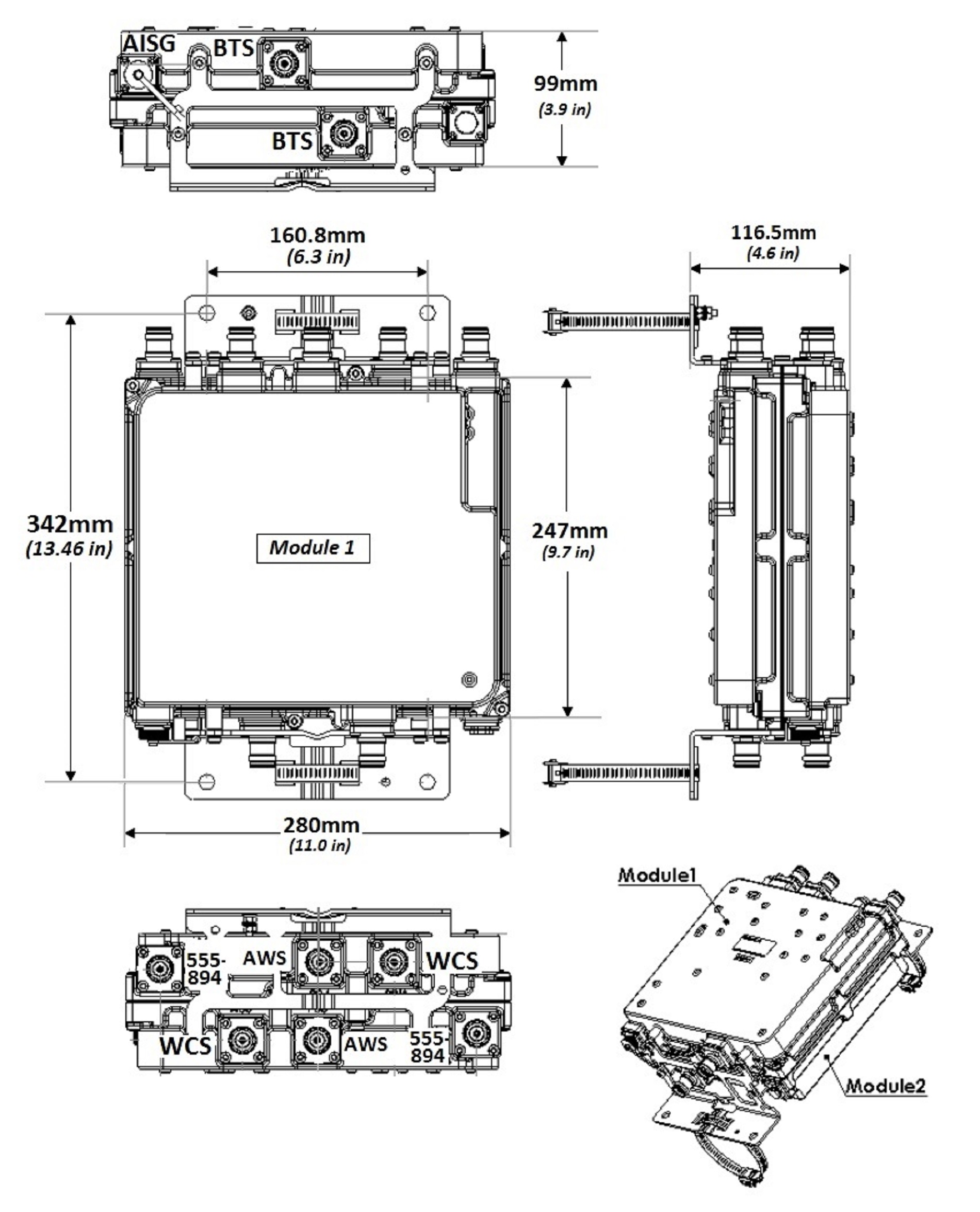
| Height | 247 mm | 9.724 in |
| Width | 280 mm | 11.024 in |
| Depth | 99 mm | 3.898 in |
| Ground Screw Diameter | 5 mm | 0.197 in |
Outline drawing
| Click on image to enlarge. |
Electrical specifications
| License Band, Band Pass | CEL 850 | USA 700 | USA 750 |
| License Band, LNA | AWS 1700 | AWS 2000 | WCS 2300 |
Electrical specifications, dc power/alarm
| dc Switching/Redundancy | Yes |
| Lightning Surge Current | 10 kA |
| Lightning Surge Current Waveform | 8/20 waveform |
| Operating Current at Voltage | 210 mA @ 12 Vdc |
| Voltage, CWA Mode | 10–18 Vdc |
| Alarm Current, CWA Mode | 150 mA +/- 10 mA (10-18 VDC) |
Electrical specifications, aisg
| AISG Carrier | 2.176 MHz ± 100 ppm |
| AISG Connector | 8-pin DIN Female |
| AISG Connector Standard | IEC 60130-9 |
| Protocol | AISG 2.0 |
| Voltage, AISG Mode | 10–30 Vdc |
Electrical specifications
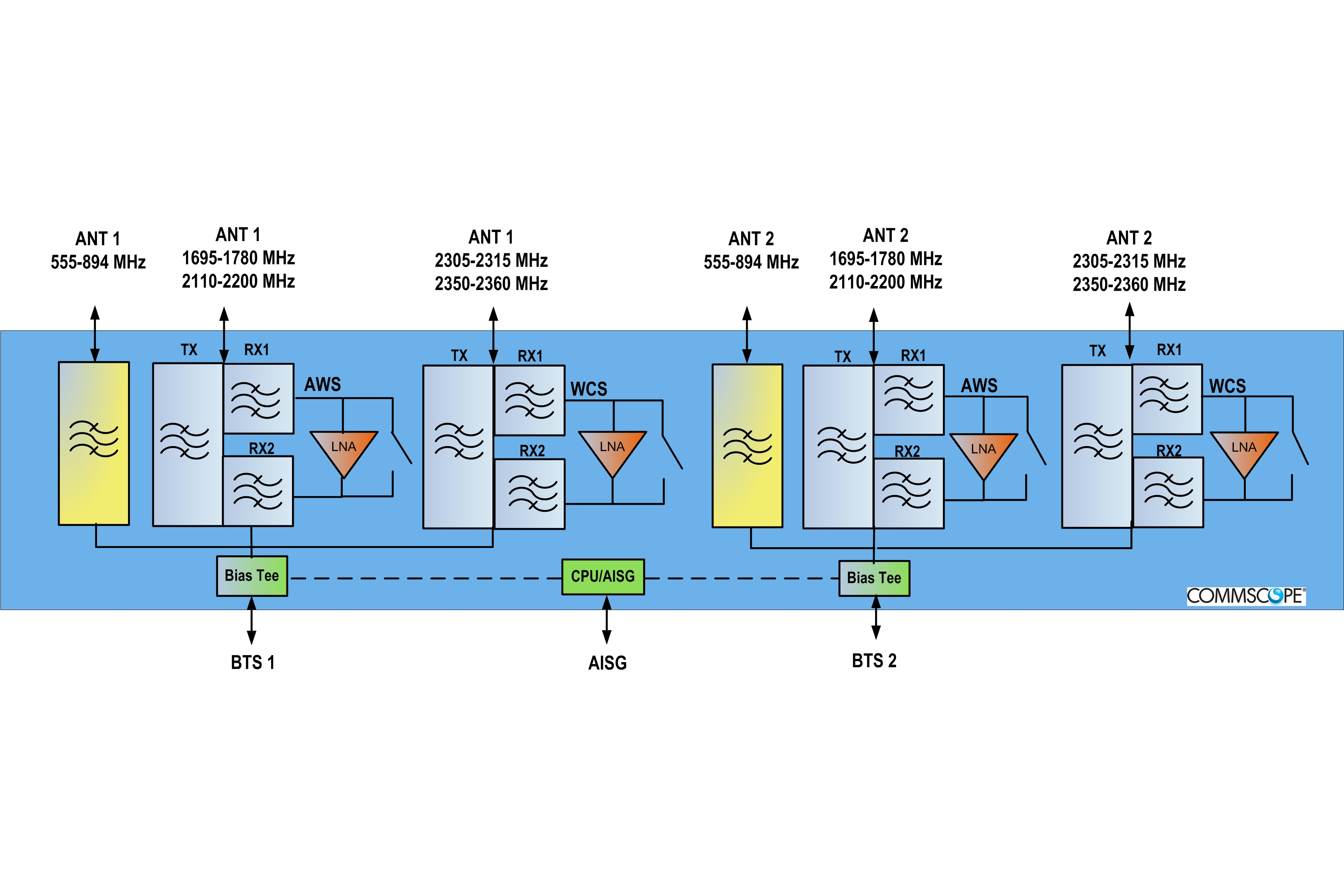
| Sub-module | 1 | 2 | 1 | 2 | 1 | 2 |
| Branch | 1 | 2 | 3 |
| Port Designation | ANT 555-894 | ANT AWS | ANT WCS |
| AISG 2.0 Device Subunit | E25A01P12 1/3 | E25A01P12 2/4 | |
| License Band | CEL 850, Band Pass USA 700, Band Pass USA 750, Band Pass | AWS 1700, LNA | WCS 2300, LNA |
Electrical specifications, band pass
| Frequency Range, MHz | 555–894 | ||
| Insertion Loss, maximum, dB | 0.20 | ||
| Return Loss, minimum, dB | 20 | ||
| Isolation, minimum, dB | 60 | ||
| Input Power, RMS, maximum, W | 200 | ||
| Input Power, PEP, maximum, W | 2,000 | ||
| 3rd Order PIM, maximum, dBc | -153 | ||
| 3rd Order PIM Test Method | 2 x 20 W CW tones |
Electrical specifications, rx uplink
| Frequency Range, MHz | 1695–1780 | 2305–2315 | |
| Gain, nominal, dB | 13.0 | 13.0 | |
| Noise Figure, typical, dB | 1.4 | 1.8 | |
| Total Group Delay, maximum, ns | 80 | 150 | |
| Return Loss, typical, dB | 20 | 21 | |
| Insertion Loss - Bypass Mode, typical, dB | 2.2 | 3.0 | |
| Return Loss - Bypass Mode, typical, dB | 18 | 18 |
Electrical specifications, tx downlink
| Frequency Range, MHz | 2110–2200 | 2350–2360 | |
| Insertion Loss, typical, dB | 0.25 | 0.50 | |
| Total Group Delay, maximum, ns | 15 | 50 | |
| Return Loss, typical, dB | 22 | 22 | |
| Input Power, RMS, maximum, W | 200 | 200 | |
| Input Power, PEP, maximum, W | 2,000 | 2,000 | |
| Higher Order PIM, maximum, dBc | -153 | -153 | |
| Higher Order PIM Test Method | 2 x 20 W CW tones | 2 x 20 W CW tones |
Block diagram
| Click on image to enlarge. |
Environmental specifications
| Operating Temperature | -40 °C to +65 °C (-40 °F to +149 °F) |
| Relative Humidity | Up to 100% |
| Corrosion Test Method | IEC 60068-2-11, 30 days |
| Ingress Protection Test Method | IEC 60529:2001, IP67 |
Packaging and weights
| Mounting Hardware Weight | 0.7 kg | 1.543 lb |
| Weight, without mounting hardware | 9.6 kg | 21.164 lb |
Product classification
| Product Type | Tower mounted amplifier |
General specifications
| RF Connector Interface | 4.3-10 Female |
| RF Connector Interface Body Style | Long neck |
Dimensions
| Height | 247 mm | 9.724 in |
| Width | 280 mm | 11.024 in |
| Depth | 99 mm | 3.898 in |
| Ground Screw Diameter | 5 mm | 0.197 in |
Electrical specifications
| License Band, Band Pass | CEL 850 | USA 700 | USA 750 |
| License Band, LNA | AWS 1700 | AWS 2000 | WCS 2300 |
Electrical specifications, dc power/alarm
| dc Switching/Redundancy | Yes |
| Lightning Surge Current | 10 kA |
| Lightning Surge Current Waveform | 8/20 waveform |
| Operating Current at Voltage | 210 mA @ 12 Vdc |
| Voltage, CWA Mode | 10–18 Vdc |
| Alarm Current, CWA Mode | 150 mA +/- 10 mA (10-18 VDC) |
Electrical specifications, aisg
| AISG Carrier | 2.176 MHz ± 100 ppm |
| AISG Connector | 8-pin DIN Female |
| AISG Connector Standard | IEC 60130-9 |
| Protocol | AISG 2.0 |
| Voltage, AISG Mode | 10–30 Vdc |
Electrical specifications
| Sub-module | 1 | 2 | 1 | 2 | 1 | 2 |
| Branch | 1 | 2 | 3 |
| Port Designation | ANT 555-894 | ANT AWS | ANT WCS |
| AISG 2.0 Device Subunit | E25A01P12 1/3 | E25A01P12 2/4 | |
| License Band | CEL 850, Band Pass; USA 700, Band Pass; USA 750, Band Pass | AWS 1700, LNA | WCS 2300, LNA |
Electrical specifications, band pass
| Frequency Range, MHz | 555–894 | ||
| Insertion Loss, maximum, dB | 0.20 | ||
| Return Loss, minimum, dB | 20 | ||
| Isolation, minimum, dB | 60 | ||
| Input Power, RMS, maximum, W | 200 | ||
| Input Power, PEP, maximum, W | 2,000 | ||
| 3rd Order PIM, maximum, dBc | -153 | ||
| 3rd Order PIM Test Method | 2 x 20 W CW tones |
Electrical specifications, rx uplink
| Frequency Range, MHz | 1695–1780 | 2305–2315 | |
| Gain, nominal, dB | 13.0 | 13.0 | |
| Noise Figure, typical, dB | 1.4 | 1.8 | |
| Total Group Delay, maximum, ns | 80 | 150 | |
| Return Loss, typical, dB | 20 | 21 | |
| Insertion Loss - Bypass Mode, typical, dB | 2.2 | 3.0 | |
| Return Loss - Bypass Mode, typical, dB | 18 | 18 |
Electrical specifications, tx downlink
| Frequency Range, MHz | 2110–2200 | 2350–2360 | |
| Insertion Loss, typical, dB | 0.25 | 0.50 | |
| Total Group Delay, maximum, ns | 15 | 50 | |
| Return Loss, typical, dB | 22 | 22 | |
| Input Power, RMS, maximum, W | 200 | 200 | |
| Input Power, PEP, maximum, W | 2,000 | 2,000 | |
| Higher Order PIM, maximum, dBc | -153 | -153 | |
| Higher Order PIM Test Method | 2 x 20 W CW tones | 2 x 20 W CW tones |
Environmental specifications
| Operating Temperature | -40 °C to +65 °C (-40 °F to +149 °F) |
| Relative Humidity | Up to 100% |
| Corrosion Test Method | IEC 60068-2-11, 30 days |
| Ingress Protection Test Method | IEC 60529:2001, IP67 |
Packaging and weights
| Mounting Hardware Weight | 0.7 kg | 1.543 lb |
| Weight, without mounting hardware | 9.6 kg | 21.164 lb |
| Click on image to enlarge. |
| Click on image to enlarge. |
Installation & videos
Installation instruction
Filter Products – Designed for PIM Excellence

Filter Products – Designed for PIM Excellence
Documentation & downloads