VV-65B-R1B-V2
4-port sector antenna, 4x 1695–2690 MHz, 65° HPBW, 1x RET and internal Bias-T on first highband port. The two highband arrays utilize a common tilt.

Features and benefits
- The RET interface comprises one pair of AISG input/output ports
Specifications
General specifications
| Antenna Type | Sector |
| Band | Single band |
| Grounding Type | RF connector body grounded to reflector and mounting bracket |
| Performance Note | Outdoor usage |
| Radome Material | PVC |
| Radiator Material | Low loss circuit board |
| RF Connector Interface | 4.3-10 Female |
| RF Connector Location | Bottom |
| RF Connector Quantity, high band | 4 |
| RF Connector Quantity, mid band | 0 |
| RF Connector Quantity, low band | 0 |
| RF Connector Quantity, total | 4 |
Remote electrical tilt (ret) information
| RET Interface | 8-pin DIN Female | 8-pin DIN Male |
| RET Interface, quantity | 1 female | 1 male |
| Input Voltage | 10–30 Vdc |
| Internal Bias Tee | Port 1 |
| Internal RET | High band (1) |
| Power Consumption, idle state, maximum | 2 W |
| Power Consumption, normal conditions, maximum | 13 W |
| Protocol | 3GPP/AISG 2.0 (Single RET) |
Dimensions
| Width | 305 mm | 12.008 in |
| Depth | 118 mm | 4.646 in |
| Length | 1786 mm | 70.315 in |
| Net Weight, without mounting kit | 13.4 kg | 29.542 lb |
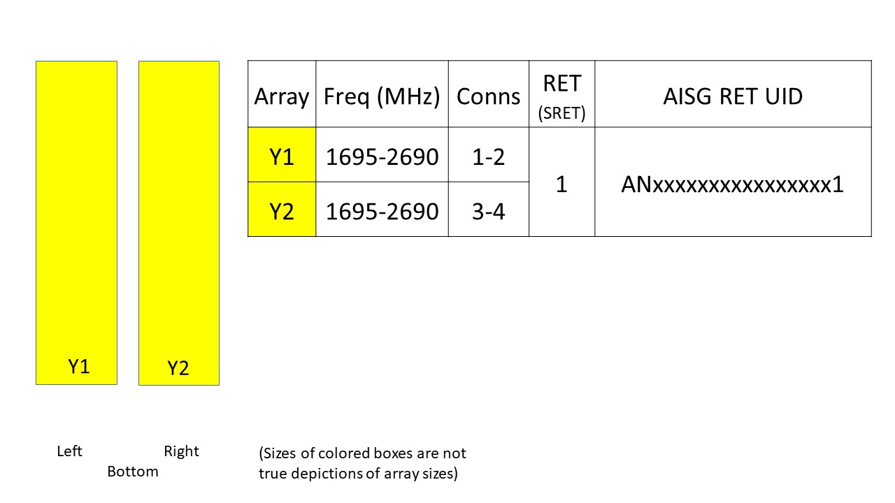
Array layout
| Click on image to enlarge. |
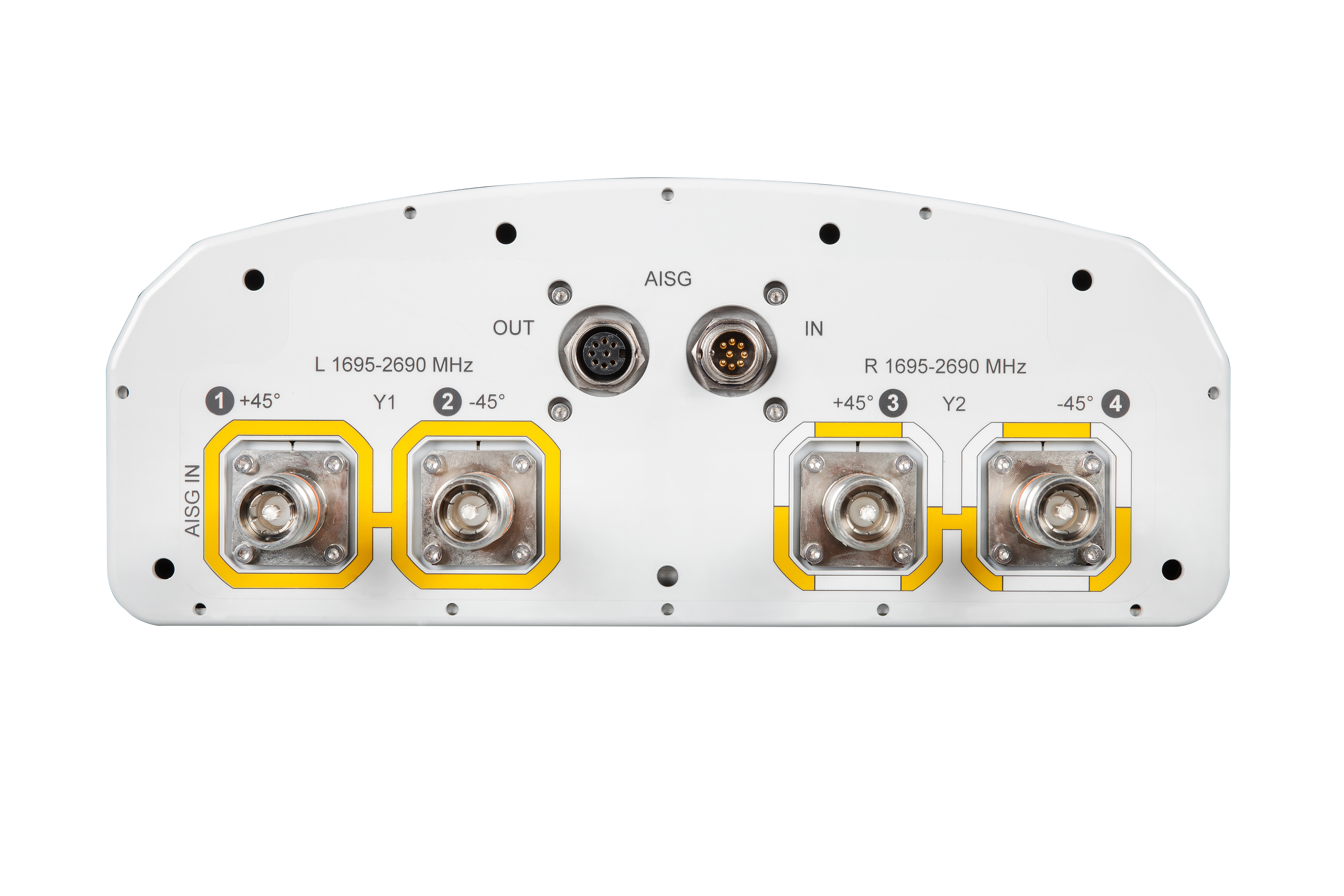
Port configuration
| Click on image to enlarge. |
Electrical specifications
| Impedance | 50 ohm |
| Operating Frequency Band | 1695 – 2690 MHz |
| Polarization | ±45° |
| Total Input Power, maximum | 400 W @ 50 °C |
Electrical specifications
| Frequency Band, MHz | 1695–1880 | 1850–1990 | 1920–2200 | 2300–2500 | 2500–2690 |
| Gain, dBi | 18.3 | 18.9 | 19.1 | 19.3 | 19.5 |
| Beamwidth, Horizontal, degrees | 66 | 66 | 66 | 61 | 57 |
| Beamwidth, Vertical, degrees | 5.6 | 5.2 | 4.9 | 4.3 | 4.1 |
| Beam Tilt, degrees | 2–12 | 2–12 | 2–12 | 2–12 | 2–12 |
| USLS (First Lobe), dB | 19 | 19 | 18 | 17 | 18 |
| Front-to-Back Ratio at 180°, dB | 32 | 34 | 36 | 35 | 36 |
| CPR at Boresight, dB | 16 | 18 | 18 | 21 | 19 |
| Isolation, Cross Polarization, dB | 30 | 30 | 30 | 30 | 30 |
| Isolation, Inter-band, dB | 30 | 30 | 30 | 30 | 30 |
| VSWR | Return loss, dB | 1.5 | 14.0 | 1.5 | 14.0 | 1.5 | 14.0 | 1.5 | 14.0 | 1.5 | 14.0 |
| PIM, 3rd Order, 2 x 20 W, dBc | -150 | -150 | -150 | -150 | -150 |
| Input Power per Port, maximum, watts | 350 | 350 | 350 | 350 | 300 |
Mechanical specifications
| Wind Loading @ Velocity, frontal | 696.0 N @ 150 km/h (156.5 lbf @ 150 km/h) |
| Wind Loading @ Velocity, lateral | 163.0 N @ 150 km/h (36.6 lbf @ 150 km/h) |
| Wind Loading @ Velocity, rear | 761.0 N @ 150 km/h (171.1 lbf @ 150 km/h) |
| Wind Speed, maximum | 241 km/h (150 mph) |
Packaging and weights
| Width, packed | 410 mm | 16.142 in |
| Depth, packed | 270 mm | 10.63 in |
| Length, packed | 1955 mm | 76.969 in |
| Weight, gross | 21 kg | 46.297 lb |
Regulatory compliance/certifications
| Agency | Classification |
|
CE
|
Compliant with the relevant CE product directives |
| ISO 9001:2015 | Designed, manufactured and/or distributed under this quality management system |
General specifications
| Antenna Type | Sector |
| Band | Single band |
| Grounding Type | RF connector body grounded to reflector and mounting bracket |
| Performance Note | Outdoor usage |
| Radome Material | PVC |
| Radiator Material | Low loss circuit board |
| RF Connector Interface | 4.3-10 Female |
| RF Connector Location | Bottom |
| RF Connector Quantity, high band | 4 |
| RF Connector Quantity, mid band | 0 |
| RF Connector Quantity, low band | 0 |
| RF Connector Quantity, total | 4 |
Remote electrical tilt (ret) information
| RET Interface | 8-pin DIN Female | 8-pin DIN Male |
| RET Interface, quantity | 1 female | 1 male |
| Input Voltage | 10–30 Vdc |
| Internal Bias Tee | Port 1 |
| Internal RET | High band (1) |
| Power Consumption, idle state, maximum | 2 W |
| Power Consumption, normal conditions, maximum | 13 W |
| Protocol | 3GPP/AISG 2.0 (Single RET) |
Dimensions
| Width | 305 mm | 12.008 in |
| Depth | 118 mm | 4.646 in |
| Length | 1786 mm | 70.315 in |
| Net Weight, without mounting kit | 13.4 kg | 29.542 lb |
Electrical specifications
| Impedance | 50 ohm |
| Operating Frequency Band | 1695 – 2690 MHz |
| Polarization | ±45° |
| Total Input Power, maximum | 400 W @ 50 °C |
Electrical specifications
| Frequency Band, MHz | 1695–1880 | 1850–1990 | 1920–2200 | 2300–2500 | 2500–2690 |
| Gain, dBi | 18.3 | 18.9 | 19.1 | 19.3 | 19.5 |
| Beamwidth, Horizontal, degrees | 66 | 66 | 66 | 61 | 57 |
| Beamwidth, Vertical, degrees | 5.6 | 5.2 | 4.9 | 4.3 | 4.1 |
| Beam Tilt, degrees | 2–12 | 2–12 | 2–12 | 2–12 | 2–12 |
| USLS (First Lobe), dB | 19 | 19 | 18 | 17 | 18 |
| Front-to-Back Ratio at 180°, dB | 32 | 34 | 36 | 35 | 36 |
| CPR at Boresight, dB | 16 | 18 | 18 | 21 | 19 |
| Isolation, Cross Polarization, dB | 30 | 30 | 30 | 30 | 30 |
| Isolation, Inter-band, dB | 30 | 30 | 30 | 30 | 30 |
| VSWR | Return loss, dB | 1.5 | 14.0 | 1.5 | 14.0 | 1.5 | 14.0 | 1.5 | 14.0 | 1.5 | 14.0 |
| PIM, 3rd Order, 2 x 20 W, dBc | -150 | -150 | -150 | -150 | -150 |
| Input Power per Port, maximum, watts | 350 | 350 | 350 | 350 | 300 |
Mechanical specifications
| Wind Loading @ Velocity, frontal | 696.0 N @ 150 km/h (156.5 lbf @ 150 km/h) |
| Wind Loading @ Velocity, lateral | 163.0 N @ 150 km/h (36.6 lbf @ 150 km/h) |
| Wind Loading @ Velocity, rear | 761.0 N @ 150 km/h (171.1 lbf @ 150 km/h) |
| Wind Speed, maximum | 241 km/h (150 mph) |
Packaging and weights
| Width, packed | 410 mm | 16.142 in |
| Depth, packed | 270 mm | 10.63 in |
| Length, packed | 1955 mm | 76.969 in |
| Weight, gross | 21 kg | 46.297 lb |
| Click on image to enlarge. |
| Click on image to enlarge. |
Regulatory compliance/certifications
| Agency | Classification |
|
CE
|
Compliant with the relevant CE product directives |
| ISO 9001:2015 | Designed, manufactured and/or distributed under this quality management system |
Installation & videos
Installation instruction
Documentation & downloads
Assembly drawing
Product information
Product specification
Assembly drawing
Product compliance documentation
Product information
Product specification
Related products & accessories
Included products
Base station antennas
-
![]() BSAMNT-F Wide Profile Antenna Fixed Tilt Mounting Kit for 2.4 - 4.5 in (60 - 115 mm) OD round members.
BSAMNT-F Wide Profile Antenna Fixed Tilt Mounting Kit for 2.4 - 4.5 in (60 - 115 mm) OD round members.
Related products
Base station antennas
-
![]() AEKTMNT Mounting Kit for 2.4 - 4.5 in (60 - 115 mm) OD round members
AEKTMNT Mounting Kit for 2.4 - 4.5 in (60 - 115 mm) OD round members -
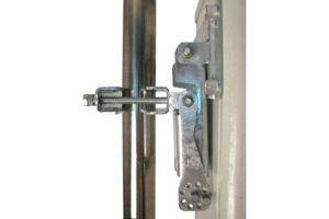
![]() BSAMNT-1 Wide Profile Antenna Downtilt Mounting Kit for 2.4 - 4.5 in (60 - 115 mm) OD round members. Kit contains one scissor top bracket set and one bottom bracket set.
BSAMNT-1 Wide Profile Antenna Downtilt Mounting Kit for 2.4 - 4.5 in (60 - 115 mm) OD round members. Kit contains one scissor top bracket set and one bottom bracket set. -
![]() BSAMNT-3 Wide Profile Antenna Downtilt Mounting Kit for 2.4 - 4.5 in (60 - 115 mm) OD round members. Kit contains one scissor top bracket set and one bottom bracket set.
BSAMNT-3 Wide Profile Antenna Downtilt Mounting Kit for 2.4 - 4.5 in (60 - 115 mm) OD round members. Kit contains one scissor top bracket set and one bottom bracket set. -
![]() BSAMNT-4 Wide Profile Antenna Downtilt Mounting Kit for 2.4 - 4.5 in (60 - 115 mm) OD round members. Kit contains one scissor top bracket set and one bottom bracket set.
BSAMNT-4 Wide Profile Antenna Downtilt Mounting Kit for 2.4 - 4.5 in (60 - 115 mm) OD round members. Kit contains one scissor top bracket set and one bottom bracket set.
-
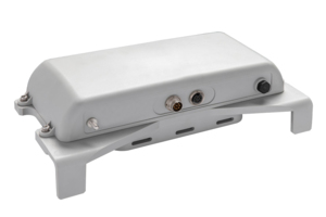
![]() APS-XT Antenna Orientation and Location Sensing System
APS-XT Antenna Orientation and Location Sensing System
Included products
Base station antennas
-
![]() BSAMNT-F Wide Profile Antenna Fixed Tilt Mounting Kit for 2.4 - 4.5 in (60 - 115 mm) OD round members.
BSAMNT-F Wide Profile Antenna Fixed Tilt Mounting Kit for 2.4 - 4.5 in (60 - 115 mm) OD round members.
Related products
Base station antennas
-
![]() AEKTMNT Mounting Kit for 2.4 - 4.5 in (60 - 115 mm) OD round members
AEKTMNT Mounting Kit for 2.4 - 4.5 in (60 - 115 mm) OD round members -
![]() BSAMNT-1 Wide Profile Antenna Downtilt Mounting Kit for 2.4 - 4.5 in (60 - 115 mm) OD round members. Kit contains one scissor top bracket set and one bottom bracket set.
BSAMNT-1 Wide Profile Antenna Downtilt Mounting Kit for 2.4 - 4.5 in (60 - 115 mm) OD round members. Kit contains one scissor top bracket set and one bottom bracket set. -
![]() BSAMNT-3 Wide Profile Antenna Downtilt Mounting Kit for 2.4 - 4.5 in (60 - 115 mm) OD round members. Kit contains one scissor top bracket set and one bottom bracket set.
BSAMNT-3 Wide Profile Antenna Downtilt Mounting Kit for 2.4 - 4.5 in (60 - 115 mm) OD round members. Kit contains one scissor top bracket set and one bottom bracket set. -
![]() BSAMNT-4 Wide Profile Antenna Downtilt Mounting Kit for 2.4 - 4.5 in (60 - 115 mm) OD round members. Kit contains one scissor top bracket set and one bottom bracket set.
BSAMNT-4 Wide Profile Antenna Downtilt Mounting Kit for 2.4 - 4.5 in (60 - 115 mm) OD round members. Kit contains one scissor top bracket set and one bottom bracket set.
-
![]() APS-XT Antenna Orientation and Location Sensing System
APS-XT Antenna Orientation and Location Sensing System