NHH-55B-HG-R2B
6-port Next Generation PerforMax™ sector antenna, 2x 698–896 and 4x 1695–2200 MHz, 55° HPBW, 2x RETs and 2x SBTs

Features and benefits
- Antenna optimized for higher gain with superior radiation efficiency
- Designed to reduce SUB 1 alarm triggers with pattern consistency between low band and mid band
- Superior patterns for enhanced interference mitigation resulting in improved SINR, higher throughput, and more capacity
- Interleaved dipole technology results into an attractive, low wind load mechanical package
- Internal SBTs allow remote RET control from the radio over the RF jumper cable
- Powered by Andrew's SEED® technology (Sustainable Energy Efficient Design)
- Best in class PIM immunity
Specifications
General specifications
| Antenna Type | Sector |
| Band | Multiband |
| Color | Light Gray (RAL 7035) |
| Grounding Type | RF connector inner conductor and body grounded to reflector and mounting bracket |
| Performance Note | Outdoor usage |
| Radome Material | Fiberglass, UV resistant |
| Radiator Material | Aluminum | Low loss circuit board |
| Reflector Material | Aluminum |
| RF Connector Interface | 4.3-10 Female |
| RF Connector Location | Bottom |
| RF Connector Quantity, mid band | 4 |
| RF Connector Quantity, low band | 2 |
| RF Connector Quantity, total | 6 |
Remote electrical tilt (ret) information
| RET Hardware | CommRET v2 |
| RET Interface | 4x 8 pin connector as per IEC 60130-9 Daisy chain in: Male / Daisy chain out: Female Pin3: RS485A(AISG_B), Pin5: RS485B(AISG_A), Pin6: DC 10~30V, Pin7: DC_ Return |
| RET Interface, quantity | 2 female | 2 male |
| Input Voltage | 10–30 Vdc |
| Internal Bias Tee | Port 1 | Port 3 |
| Internal RET | Low band (1) | Mid band (1) |
| Power Consumption, active state, maximum | 10 W |
| Power Consumption, idle state, maximum | 2 W |
| Protocol | 3GPP/AISG 2.0 (Single RET) |
Dimensions
| Width | 395 mm | 15.551 in |
| Depth | 228 mm | 8.976 in |
| Length | 1828 mm | 71.969 in |
| Net Weight, without mounting kit | 26 kg | 57.320 lb |
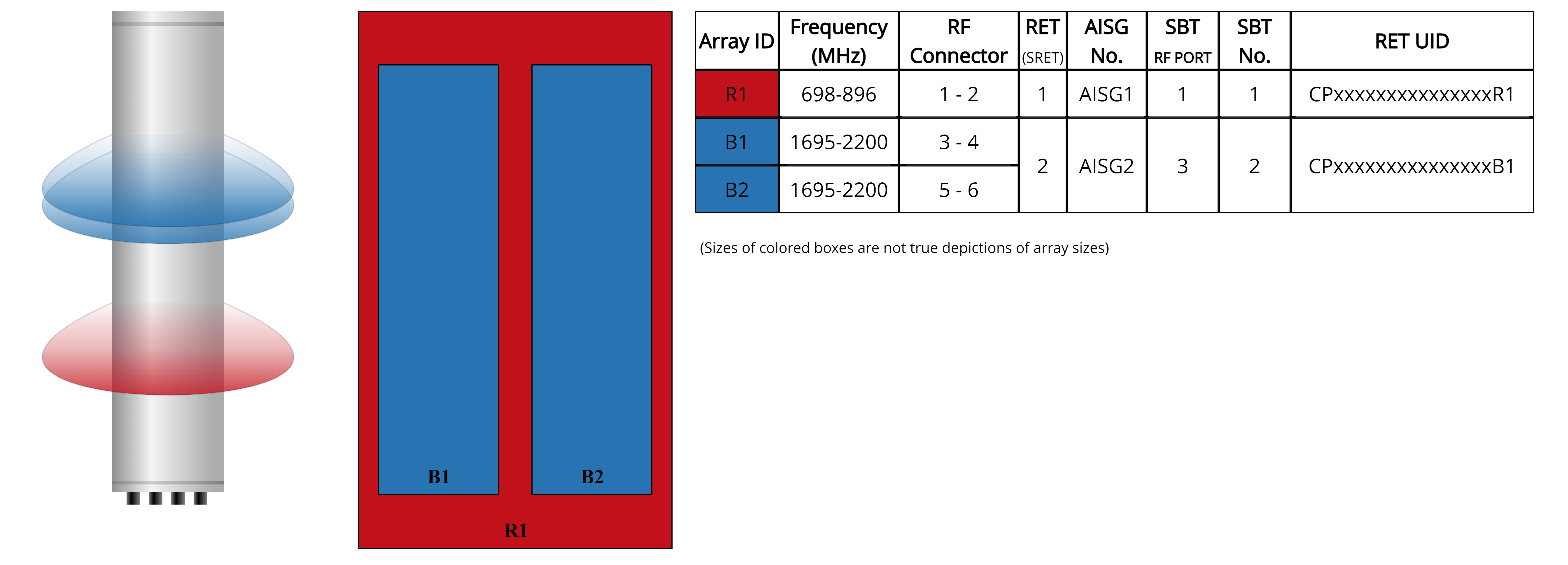
Array layout
| Click on image to enlarge. |
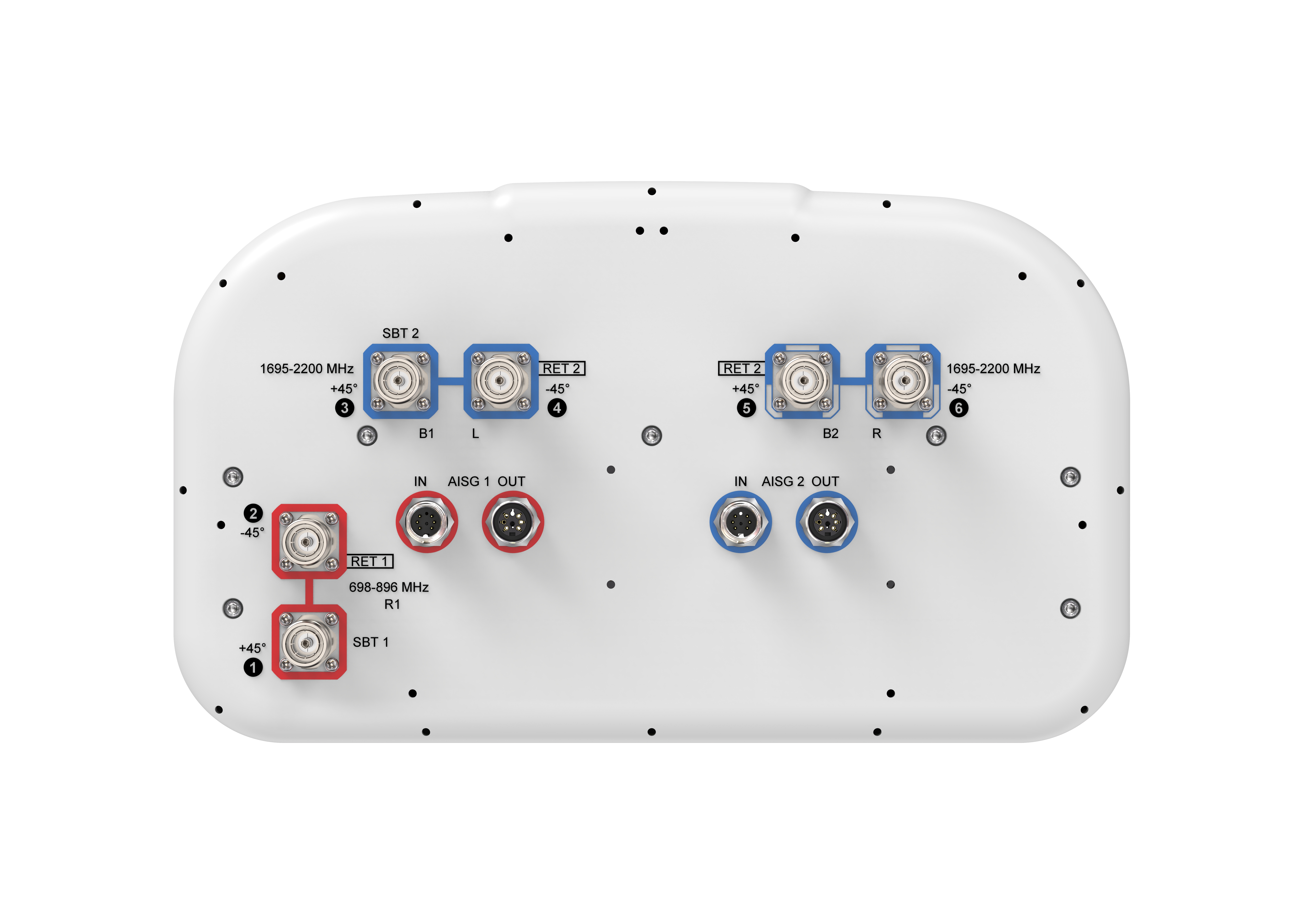
Port configuration
| Click on image to enlarge. |
Electrical specifications
| Impedance | 50 ohm |
| Operating Frequency Band | 698 – 896 MHz | 1695 – 2200 MHz |
| Polarization | ±45° |
| Total Input Power, maximum | 900 W @ 50 °C |
Electrical specifications
| R1 | R1 | B1,B2 | B1,B2 | B1,B2 | |
| Frequency Band, MHz | 698–806 | 806–896 | 1695–1880 | 1850–1990 | 1920–2200 |
| RF Port | 1,2 | 1,2 | 3,4,5,6 | 3,4,5,6 | 3,4,5,6 |
| Gain, Maximum, dBi | 16.100 | 16.200 | 18.700 | 19.200 | 19.700 |
| Gain, dBi | 15.8 | 15.9 | 18.4 | 18.8 | 19.3 |
| Beamwidth, Horizontal, degrees | 58 | 54 | 56 | 55 | 52 |
| Beamwidth, Vertical, degrees | 11.8 | 10.3 | 5.6 | 5.3 | 5 |
| Beam Tilt, degrees | 0–14 | 0–14 | 0–7 | 0–7 | 0–7 |
| USLS (First Lobe), dB | 16 | 16 | 17 | 17 | 16 |
| Front-to-Back Ratio at 180°, dB | 26 | 28 | 32 | 30 | 31 |
| CPR at Boresight, dB | 23 | 18 | 21 | 21 | 21 |
| Isolation, Cross Polarization, dB | 25 | 25 | 25 | 25 | 25 |
| VSWR | Return loss, dB | 1.5 | 14.0 | 1.5 | 14.0 | 1.5 | 14.0 | 1.5 | 14.0 | 1.5 | 14.0 |
| PIM, 3rd Order, typical, 2 x 20 W, dBc | -153 | -153 | -153 | -153 | -153 |
| Input Power per Port at 50°C, maximum, watts | 250 | 250 | 200 | 200 | 200 |
Mechanical specifications
| Wind Loading @ Velocity, frontal | 272.0 N @ 150 km/h (61.1 lbf @ 150 km/h) |
| Wind Loading @ Velocity, lateral | 244.0 N @ 150 km/h (54.9 lbf @ 150 km/h) |
| Wind Loading @ Velocity, maximum | 547.0 N @ 150 km/h (123.0 lbf @ 150 km/h) |
| Wind Loading @ Velocity, rear | 311.0 N @ 150 km/h (69.9 lbf @ 150 km/h) |
| Wind Speed, maximum | 241 km/h (150 mph) |
Packaging and weights
| Width, packed | 505 mm | 19.882 in |
| Depth, packed | 386 mm | 15.197 in |
| Length, packed | 1960 mm | 77.165 in |
| Weight, gross | 39.7 kg | 87.523 lb |
Regulatory compliance/certifications
| Agency | Classification |
|
CHINA-ROHS
|
Above maximum concentration value |
| ROHS | Compliant/Exempted |
| UK-ROHS | Compliant/Exempted |
General specifications
| Antenna Type | Sector |
| Band | Multiband |
| Color | Light Gray (RAL 7035) |
| Grounding Type | RF connector inner conductor and body grounded to reflector and mounting bracket |
| Performance Note | Outdoor usage |
| Radome Material | Fiberglass, UV resistant |
| Radiator Material | Aluminum | Low loss circuit board |
| Reflector Material | Aluminum |
| RF Connector Interface | 4.3-10 Female |
| RF Connector Location | Bottom |
| RF Connector Quantity, mid band | 4 |
| RF Connector Quantity, low band | 2 |
| RF Connector Quantity, total | 6 |
Remote electrical tilt (ret) information
| RET Hardware | CommRET v2 |
| RET Interface | 4x 8 pin connector as per IEC 60130-9 Daisy chain in: Male / Daisy chain out: Female Pin3: RS485A(AISG_B), Pin5: RS485B(AISG_A), Pin6: DC 10~30V, Pin7: DC_ Return |
| RET Interface, quantity | 2 female | 2 male |
| Input Voltage | 10–30 Vdc |
| Internal Bias Tee | Port 1 | Port 3 |
| Internal RET | Low band (1) | Mid band (1) |
| Power Consumption, active state, maximum | 10 W |
| Power Consumption, idle state, maximum | 2 W |
| Protocol | 3GPP/AISG 2.0 (Single RET) |
Dimensions
| Width | 395 mm | 15.551 in |
| Depth | 228 mm | 8.976 in |
| Length | 1828 mm | 71.969 in |
| Net Weight, without mounting kit | 26 kg | 57.320 lb |
Electrical specifications
| Impedance | 50 ohm |
| Operating Frequency Band | 698 – 896 MHz | 1695 – 2200 MHz |
| Polarization | ±45° |
| Total Input Power, maximum | 900 W @ 50 °C |
Electrical specifications
| R1 | R1 | B1,B2 | B1,B2 | B1,B2 | |
| Frequency Band, MHz | 698–806 | 806–896 | 1695–1880 | 1850–1990 | 1920–2200 |
| RF Port | 1,2 | 1,2 | 3,4,5,6 | 3,4,5,6 | 3,4,5,6 |
| Gain, Maximum, dBi | 16.100 | 16.200 | 18.700 | 19.200 | 19.700 |
| Gain, dBi | 15.8 | 15.9 | 18.4 | 18.8 | 19.3 |
| Beamwidth, Horizontal, degrees | 58 | 54 | 56 | 55 | 52 |
| Beamwidth, Vertical, degrees | 11.8 | 10.3 | 5.6 | 5.3 | 5 |
| Beam Tilt, degrees | 0–14 | 0–14 | 0–7 | 0–7 | 0–7 |
| USLS (First Lobe), dB | 16 | 16 | 17 | 17 | 16 |
| Front-to-Back Ratio at 180°, dB | 26 | 28 | 32 | 30 | 31 |
| CPR at Boresight, dB | 23 | 18 | 21 | 21 | 21 |
| Isolation, Cross Polarization, dB | 25 | 25 | 25 | 25 | 25 |
| VSWR | Return loss, dB | 1.5 | 14.0 | 1.5 | 14.0 | 1.5 | 14.0 | 1.5 | 14.0 | 1.5 | 14.0 |
| PIM, 3rd Order, typical, 2 x 20 W, dBc | -153 | -153 | -153 | -153 | -153 |
| Input Power per Port at 50°C, maximum, watts | 250 | 250 | 200 | 200 | 200 |
Mechanical specifications
| Wind Loading @ Velocity, frontal | 272.0 N @ 150 km/h (61.1 lbf @ 150 km/h) |
| Wind Loading @ Velocity, lateral | 244.0 N @ 150 km/h (54.9 lbf @ 150 km/h) |
| Wind Loading @ Velocity, maximum | 547.0 N @ 150 km/h (123.0 lbf @ 150 km/h) |
| Wind Loading @ Velocity, rear | 311.0 N @ 150 km/h (69.9 lbf @ 150 km/h) |
| Wind Speed, maximum | 241 km/h (150 mph) |
Packaging and weights
| Width, packed | 505 mm | 19.882 in |
| Depth, packed | 386 mm | 15.197 in |
| Length, packed | 1960 mm | 77.165 in |
| Weight, gross | 39.7 kg | 87.523 lb |
| Click on image to enlarge. |
| Click on image to enlarge. |
Regulatory compliance/certifications
| Agency | Classification |
|
CHINA-ROHS
|
Above maximum concentration value |
| ROHS | Compliant/Exempted |
| UK-ROHS | Compliant/Exempted |
Documentation & downloads
Assembly drawing
Product information
Product specification
Assembly drawing
Product compliance documentation
Product information
Product specification
Related products & accessories
Included products
Base station antennas
-
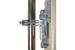
![]() BSAMNT-3 Wide Profile Antenna Downtilt Mounting Kit for 2.4 - 4.5 in (60 - 115 mm) OD round members. Kit contains one scissor top bracket set and one bottom bracket set.
BSAMNT-3 Wide Profile Antenna Downtilt Mounting Kit for 2.4 - 4.5 in (60 - 115 mm) OD round members. Kit contains one scissor top bracket set and one bottom bracket set.
Related products
Base station antennas
-
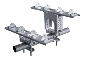
![]() BSAMNT-SBS-2-2 Side-By-Side Mounting Kit to mount two antennas on a pipe with 2.375 - 4.5 inch (60 – 115 mm) diameter
BSAMNT-SBS-2-2 Side-By-Side Mounting Kit to mount two antennas on a pipe with 2.375 - 4.5 inch (60 – 115 mm) diameter
Included products
Base station antennas
-
![]() BSAMNT-3 Wide Profile Antenna Downtilt Mounting Kit for 2.4 - 4.5 in (60 - 115 mm) OD round members. Kit contains one scissor top bracket set and one bottom bracket set.
BSAMNT-3 Wide Profile Antenna Downtilt Mounting Kit for 2.4 - 4.5 in (60 - 115 mm) OD round members. Kit contains one scissor top bracket set and one bottom bracket set.
Related products
Base station antennas
-
![]() BSAMNT-SBS-2-2 Side-By-Side Mounting Kit to mount two antennas on a pipe with 2.375 - 4.5 inch (60 – 115 mm) diameter
BSAMNT-SBS-2-2 Side-By-Side Mounting Kit to mount two antennas on a pipe with 2.375 - 4.5 inch (60 – 115 mm) diameter